FLOATING WIND TURBINE MODEL
This project resulted in coupled model for floating off-shore wind turbines, using the DTU 10-MW machine [1] as an example. The idea put forward is to employ high fidelity Navier-Stokes solvers for air and water. For this reason, the Helicopter Multi-Block solver [2] was used for air, and the Smoothed Particles Hydrodynamic method [3] was used for water. The multi-body solver was implemented to solve for the wind turbine dynamics. All solvers were validated before coupling, and coupled algorithm was implemented using Message Passing Interface (MPI) to bring all solvers into one framework.
The aerodynamic grid consisted of 8M cells, where 24 cells are used in the boundary layer, and 166 cells were distributed around the aerofoil section. The hydrodynamic domain was discretized using 5M particles with initial uniform spacing of d = 0.625m.
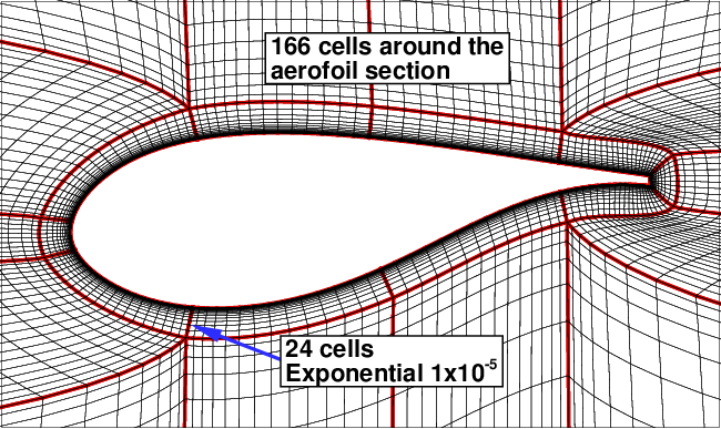
Slice through 8M mesh used to solve for aerodynamic loads.
The floating wind turbine was placed in a shallow tank of length 500m, width 150m and height 30m. The tank was filled with water to a depth of 20.6m. The waves were generated using a paddle on one side, and dissipated using a beach-like slope on the other side of the tank. Waves are generated to represent the specific sea state corresponding to a given wind speed. Based on the measurements of annual sea state occurrences in the North Atlantic and North Pacific, the wind speed of 11m/s corresponds to a sea state 4 with a mean wave height of 1.88m and a period of 8.8s.
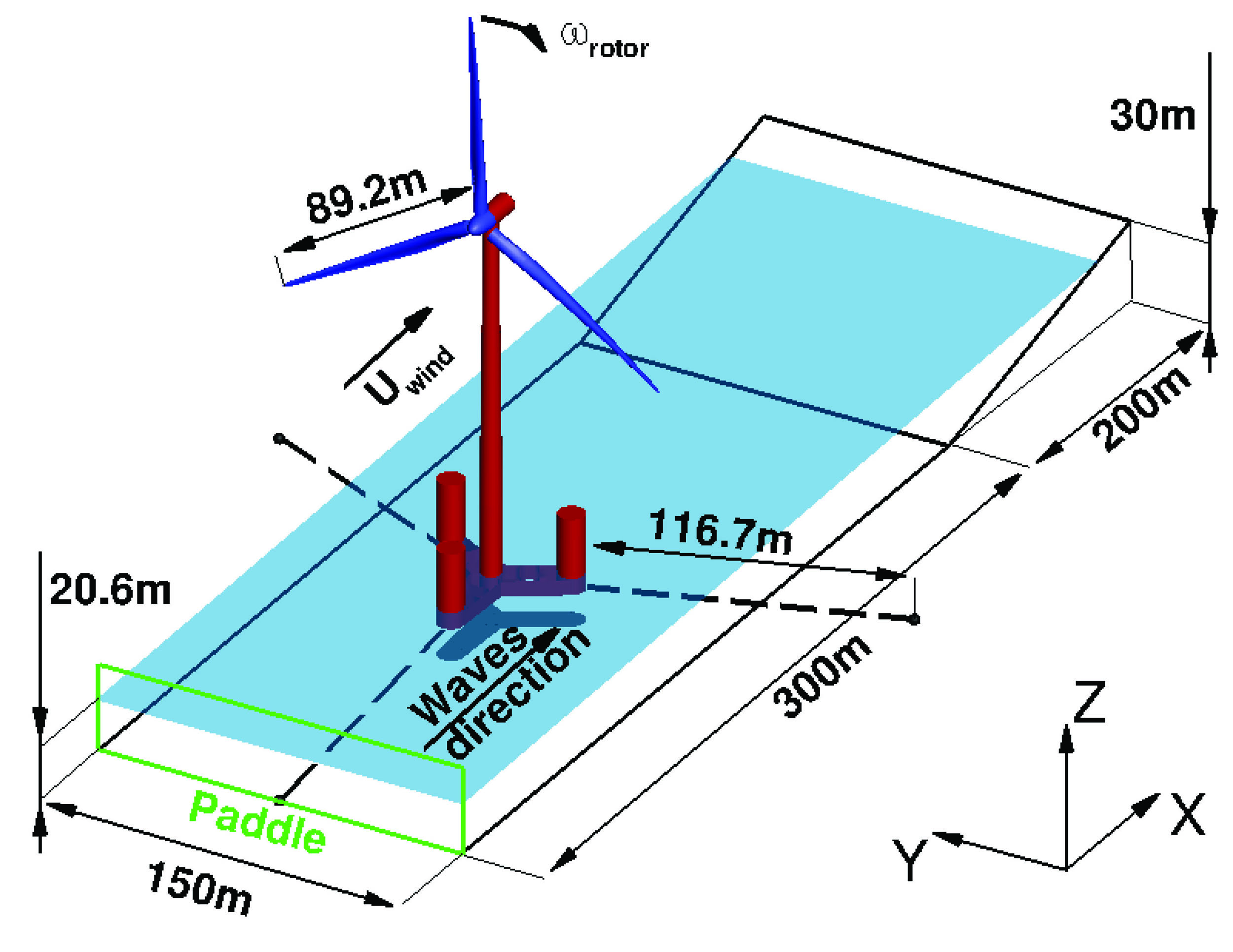
The floating wind turbine model placed in a shallow tank. Mooring lines are shown with dashed lines.
The results showed that the employed floating turbine under studied conditions did not enter a vortex ring state. A turbulent wake state was encountered, but only at the initial pitching phase. The gyroscopic effects were also small for studied system, and did not cause significant rotations due to large inertia of the employed floater. For more derails regarding this project please refer to article of our employee Vladimir Leble [4]. You may also request more information using contact form.
Results of coupled simulation of 10MW floating wind turbine. Contours on the rotor correspond to pressure coefficient Cp, contours on the water surface correspond to surface elevation z in meters.
[1] Bak Ch., Zahle F., Bitsche R., Kim T., Yde A., Henriksen L.C., Hansen M.H., Blasques J.P., Gaunaa M., Natarajan A., The DTU 10-MW Reference Wind Turbine. https://www.hawc2.dk/Download/HAWC2-Model/DTU-10-MW-Reference-Wind-Turbine
[2] Steijl R., Barakos G., and Badcock K. A framework for cfd analysis of helicopter rotors in hover and forward flight. International Journal for Numerical Methods in Fluids, 51(8):819–847, 2006. https://onlinelibrary.wiley.com/doi/abs/10.1002/fld.1086
[3] SPHysics, a Smoothed Particle Hydrodynamics numerical model developed to study free-surface flows. https://dual.sphysics.org/sphysics-project/
[4] Leble V., and Barakos G., Demonstration of a coupled floating offshore wind turbine analysis with high-fidelity methods, Journal of Fluids and Structures, Volume 62, pp. 272–293, April 2016, ISSN 0889-9746, DOI:10.1016/j.jfluidstructs.2016.02.001.